• Welcome to the ElgrandOC forum.

    You will find that the majority of the forum is locked, but do not worry. You can unlock more content by registering to the forum completely free. Sign up is automatic, does not require email confirmation and is instant. Feel free to browse through the sections to see what topics have been covered before you register.
    You can register for an account by CLICKING HERE

    Once you have registered, you will unlock more of the forum content. You will not unlock all of the content until you have reached 10 posts. This is to give you an opportunity to chat to existing members and help to integrate you into the forum community.
    We are a friendly and helpful community and there is a wealth of infomation contained within the forum. Please feel free to register, introduce yourself and get to know your fellow members.

    Feel free to look at the Frequently Asked Questions section, the Meets/Events section and the Competition Section without having to register.
    We look forward to getting to know you and help you with any questions or problemd you have with your Elgrand.

Fuel gauge recall

I'm now a bit stuck - the Nissan EU contact said that he'd phoned a couple of garages and they were not able to do it. I'm not really sure what Nissan EU helpdesk are doing - they just seem to be a buffer with the dealerships.

Has anyone apart from Beccy99 successfully had the recall done in a UK garage in the last year or two? Has anyone worked out what the repair is, or equally done another repair like wiring across the bad solder joint?
I'm not sure if I can buy a scrap dashboard cluster and move the part across... needing to preserve the odometer mileage etc. but assume that is a different circuit.

When calling Nissan EU, there is an option on the phone menu to select "complain" - but I'm not convinced that goes anywhere different! HELP!!
 
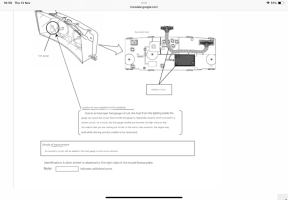
Hi Gordon @gball I’m fairly sure the unit to fix this is plug and play, so you don’t need the full instrument cluster, so if you can locate a scrapper then it should just plug in - see pic - the dark box and harness is the fix and the bit you need

IMG_0067.png
 
Hi Gordon @gball I’m fairly sure the unit to fix this is plug and play, so you don’t need the full instrument cluster, so if you can locate a scrapper then it should just plug in - see pic - the dark box and harness is the fix and the bit you need

View attachment 118279
As above
Make sure you get the harness, I’ve seen the clusters with the extra box on eBay many times but minus the harness
 
Ah, so its both the auxiliary circuit (dark grey box) and a new wiring loom. That explains - I couldn't see how the box connected into the existing cluster, and assumed it was drilled in to the circuit board underneath. If the whole loom is replaced then I can see it being a much simpler fix.

Having said that, if its really just plugging in a new lead and taping the box down, that is a 5 minute job ... why would a garage not be happy to do this??? :sob:

The other thought was, if someone had ever taken the back off the cluster, simply to find the broken track and repair it.

As an electronics person, I was a bit suspicious that the "lighting inside the gauge" could heat up the board - the cluster lights are LEDs and don't really get warm at all. I might try and open the back if it looks like it is a serviceable part (and not tamper sealed). It's been open before as the speedo was converted via a sticker - though I think thats probably the front glass rather than the rear.
 
The kit is actually the complete black rear cover panel of which the new circuit board box is a moulded part.
 
Thanks @LeStempy - but even though it's the whole black rear cover panel, is the only electrical connection via the new harness that has some extra wires broken out... or are there also other wires that go between the circuit and into the main circuit board itself? Trying to work out if all the wiring is done via the harness, or if there is actually some soldering/internal connections also.
 
Thanks @LeStempy - but even though it's the whole black rear cover panel, is the only electrical connection via the new harness that has some extra wires broken out... or are there also other wires that go between the circuit and into the main circuit board itself? Trying to work out if all the wiring is done via the harness, or if there is actually some soldering/internal connections also.
The extra loom is just an extension with a breakout plug which fits into the additional circuit board. You don't necessarily need the back cover but you do need the loom and the addition board. The only extra connection are via the breakout plug.
 
IMG_0169.jpeg

Seems to be happier on its side…….
 
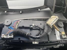
I couldn't live with that shocking photo, I just had to go and dismantle mine to take a new one!
Please ignore the shocking wiring on the left😱 that's what the dealer did fitting the Km to Mile conversion, I will have to tidy that up next time I go in there!
tempImageah863K.jpg
 
Last edited:
I'm now a bit stuck - the Nissan EU contact said that he'd phoned a couple of garages and they were not able to do it. I'm not really sure what Nissan EU helpdesk are doing - they just seem to be a buffer with the dealerships.

Has anyone apart from Beccy99 successfully had the recall done in a UK garage in the last year or two? Has anyone worked out what the repair is, or equally done another repair like wiring across the bad solder joint?
I'm not sure if I can buy a scrap dashboard cluster and move the part across... needing to preserve the odometer mileage etc. but assume that is a different circuit.

When calling Nissan EU, there is an option on the phone menu to select "complain" - but I'm not convinced that goes anywhere different! HELP!!
Hi have you managed to buy the part for cluster because ive had to buy one from Japan because i couldn't find one with the wire harness but I got mine a week ago and I just clipped the hole back plate on my clocks and all good but I need to see if its fixed or mine could be the fuel sender in the tank hope you get it sorted out
 
I'm now a bit stuck - the Nissan EU contact said that he'd phoned a couple of garages and they were not able to do it. I'm not really sure what Nissan EU helpdesk are doing - they just seem to be a buffer with the dealerships.

Has anyone apart from Beccy99 successfully had the recall done in a UK garage in the last year or two? Has anyone worked out what the repair is, or equally done another repair like wiring across the bad solder joint?
I'm not sure if I can buy a scrap dashboard cluster and move the part across... needing to preserve the odometer mileage etc. but assume that is a different circuit.

When calling Nissan EU, there is an option on the phone menu to select "complain" - but I'm not convinced that goes anywhere different! HELP!!
I have been trying to add to this message, but for some time, I have not been allowed to post. I had mine done in October. Do you still need advice?
 
I have been trying to add to this message, but for some time, I have not been allowed to post. I had mine done in October. Do you still need advice?
Hi I'm not sure why but ive managed to fix it now but I had to get a clock from Japan with the parts and cables but thank you
 
Thank you everyone! I decided the only quick answer was to buy an instrument cluster which had the harness intact. Since these are harder to find, I thought I would return the favour by checking the wiring harness with a multimeter so others can do it cheaper by splicing in the cable (if they have the black box but not the loom) I've attached pictures that hopefully help.
The loom has (unsurprisingly) most wires passing straight through. In fact only one wire breaks the connection!

There are four wires only going into the black box. Two are spliced into the loom (I'm guessing power and ground) The other two - one cuts into the female end (into the cluster), one cuts into the equivalent cable on the male which goes into the car.

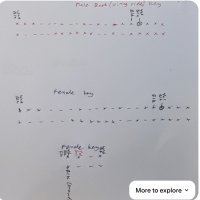
I drew up the diagram in biro - although plugs are fiddly to draw the right way round, it should be obvious if you have an existing harness, since the wires are spaced out in a clear pattern - the group you care about is a row of 6 at the end. No other orientation has this.

White + Blackstripe = connects to top left hand female (and just splices in - the wire is continuous from female to male)
Black = connects to 5th from the top right side (and just splices in - the wire is continuous from female to male)
Yellow + Blackstripe + Silver Dot = connects only to the female, 4th from top right side (I'm guessing this is the output to the meter dial)
Yellow + Greenstripe - connects only to the male, 4th from top right side (I'm guessing this is the input from the tank sensor)

So the yellow is the one which has an in and an out. The white and black appear to be just supplying power.

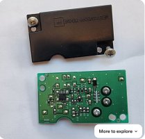
The black box has quite a few components in it - it looks like a voltage dropper (to take 12V down to something else?) and an op-amp, possibly something to make the fuel dial move more slowly to even out the reading? Who knows? Anyway, it's just 2 power wires, an "in" and an "out".

Hope this might help someone some day!
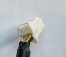
1/5 - Female connector showing wires that connect into the dash
2/5 - Female connector that joins to the new black box (4 wires only)
3/5 - Sketch of which pins connect through and which pin breaks in (yellow/green and yellow/black)
4/5 - inside of the black box (top side)
5/5 - inside of the black box (bottom side)

I couldn't get embedded image links to work, I'm afraid - so I have just popped them in as links. I realise this might now be classed in the "technical" forum - feel free to crosslink if it would be better there. Gordon
 
Thank you everyone! I decided the only quick answer was to buy an instrument cluster which had the harness intact. Since these are harder to find, I thought I would return the favour by checking the wiring harness with a multimeter so others can do it cheaper by splicing in the cable (if they have the black box but not the loom) I've attached pictures that hopefully help.
The loom has (unsurprisingly) most wires passing straight through. In fact only one wire breaks the connection!

There are four wires only going into the black box. Two are spliced into the loom (I'm guessing power and ground) The other two - one cuts into the female end (into the cluster), one cuts into the equivalent cable on the male which goes into the car.

I drew up the diagram in biro - although plugs are fiddly to draw the right way round, it should be obvious if you have an existing harness, since the wires are spaced out in a clear pattern - the group you care about is a row of 6 at the end. No other orientation has this.

White + Blackstripe = connects to top left hand female (and just splices in - the wire is continuous from female to male)
Black = connects to 5th from the top right side (and just splices in - the wire is continuous from female to male)
Yellow + Blackstripe + Silver Dot = connects only to the female, 4th from top right side (I'm guessing this is the output to the meter dial)
Yellow + Greenstripe - connects only to the male, 4th from top right side (I'm guessing this is the input from the tank sensor)

So the yellow is the one which has an in and an out. The white and black appear to be just supplying power.

The black box has quite a few components in it - it looks like a voltage dropper (to take 12V down to something else?) and an op-amp, possibly something to make the fuel dial move more slowly to even out the reading? Who knows? Anyway, it's just 2 power wires, an "in" and an "out".

Hope this might help someone some day!
1/5 - Female connector showing wires that connect into the dash
2/5 - Female connector that joins to the new black box (4 wires only)
3/5 - Sketch of which pins connect through and which pin breaks in (yellow/green and yellow/black)
4/5 - inside of the black box (top side)
5/5 - inside of the black box (bottom side)

I couldn't get embedded image links to work, I'm afraid - so I have just popped them in as links. I realise this might now be classed in the "technical" forum - feel free to crosslink if it would be better there. Gordon
Nice work.
 
Members such as yourself are the main reason why I joined in the first instance. You have clearly invested a lot of time and energy in trying to help others in the group. Many thanks for all your endeavors. This will definitely help a lot of other owners.
 
Back
Top